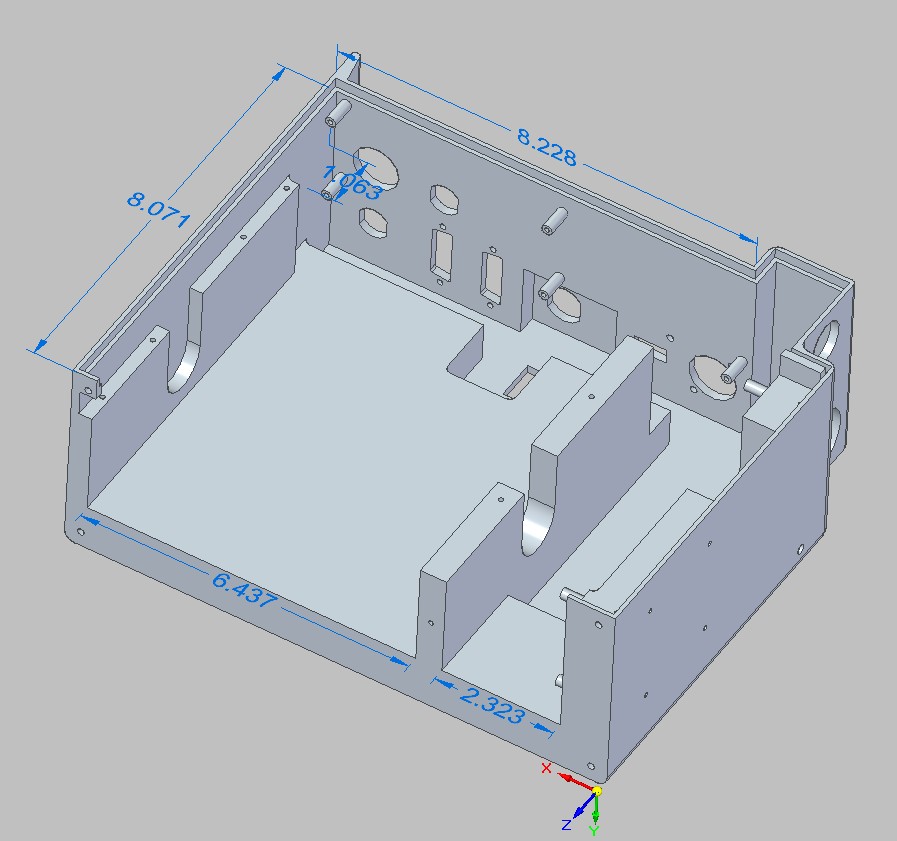
Sometimes as you wander through your daily life in the design build world you run across things periodically that irritate the heck out of you. This week all I want to do is design a transition that will go from a 13.875″ wide 16.25″ long ID rectangular base to a 12″ offset round with an overall height of 13″.
Now this is not a problem in SE until you realize that HEY, HOW do I do this and have segmented bends in the corners so I can actually produce this thing in my shop? I did not know any way to do this and in checking with support today they told me it was not an existing capability in SE. ER: 1629173 is the number of interest for you SE users who would like to see this change. Pile on guys, the squeaky wheel is the one oiled and I now have my jelly bean candidate for SEU 2014 roundtables.
In researching how to work around this I came up with two products that appear to fill the bill. Both of these claim to create and unfold various sheet metal fabrications and they can get to be quite complex especially in the “Sheet Lightning” program. They also will allow you to print out using your regular printer and standard size sheets of paper thereby making a template you can actually lay out on your sheet metal as a guide for cutting and bending. A REALLY handy thing for a whole bunch of shops to just get a single item out quickly.
“Sheet Lightning” http://www.revcad.com/Sheet5/Products/products_0.html of course is one of these. I have an older version (5.2) of this program and it does work. I have used it before and I used it again on this transition. It will allow you to output a DXF file also which you can send out for fabrication to your favorite laser guy. One thing I have never found is how to assign thickness to your metal which is pretty darned critical. I have had a question in for most of today to Revcad but no answer yet so I have no idea if this capability is in the newer versions. It is far more complicated to learn than the next program but it will allow you to do some seriously complicated things that “Plate and Sheet” in my brief examination apparently wont. It is also FAR cheaper at $150.00
“Plate and Sheet Professional” http://www.plate-n-sheet.com.au/ is the other candidate. It is far more expensive at $900+ $ AU and I feel it has design limitations that Sheet Lightning does not BUT it appears to be far more adapted to a production environment. Easier to learn and allows for thickness of material as inside, outside or neutral for the purposes of calculating layouts. At six times the cost it is quite pricy but since the other program does not apparently have thickness as an input it would be worth it in many cases especially if you start getting into heavier sheet metal or plate. In any case I downloaded V4.2 today and here is a video of just how easy this thing is to use.
I am extending an invitation to both companies to comment here to correct any errors or omissions on my part as I am not real conversant with either program. Hopefully they will respond.
UPDATE, this is from Sheet lightning.
Hi Dave,
Thanks for letting us know about this posting. My apologies for not responding sooner, it initially got mistaken for spam.
On the issue of thickness of material in Sheet Lightning we have found the best solution is for the user to use the neutral axis dimensions (inner diameter + 2x (0.5 * thickness)) to define half way through the material as the neutral axis which is perfectly adequate for most cases as most uses are for relatively thin sheet (which we would defines as: diameter > thickness * 40). In some cases where thicker material is used and greater accuracy is wanted we advise the use of a factor to give slight correction (e.g. inner diameter + 2x(f*thickness)) where the factor may typically be 0.4 – 0.5, often typically something like 0.47. This is material and forming process dependent and may be derived empirically so it is difficult to specify for every case but in the absence of empirical data through experiment there is enough advice available out there on that to help the user decide.
We have in the past enabled thickness of material and a factor as parameters that worked internally in this way but found it caused more complications (mainly by cluttering the parameter lists) than were necessary and it was simply better to train users to work this way directly.
I hope this answers your questions. Thanks for the article, it is good to see people like you taking an interest in our product/s. If you need further input please let us know.
Regards
Trevor Maddison
Revcad
5-6-14 here is a response to Dennis from Ryan Gudorf in regards to a Tee. Thanks Ryan.