Rotary valves for depositors and food sevice use quite often have a few critical measurements that need to be adhered to. The size of the rotary cutouts to match the housing cutouts and degree of angle of these around the centerline of the valve and housing cutout. The diameter and angle of the lever at the end.
Perhaps the most difficult area of creation is where two cutouts meet where they are of differing sizes and the corner rounds also differ. How do you make this geometry work? Now keep in mind this is a part to be cut on a rotary indexer on a VMC and ability of product to flow through this valve is far more important than a perfect blended set of surfaces where the two cutouts meet.
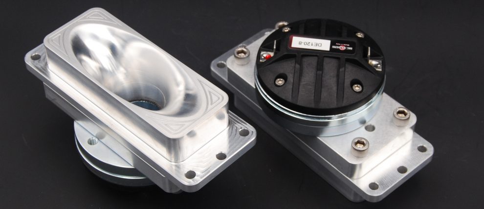
Here is the actual valve we are duplicating and while it is not real clear you can see enough to get the idea of where we want to go. In the following video the creation of the majority of the geometry and all the sketches have been done ahead of time and what I want to show is how direct editing can quickly arrive at a factory produced part condition.
I extrude remove from the top plane a cutout and apply corner rounds at this time keeping the depth of the cutout just into the part enough to create the rounds.
I can now go to the sketch on the angular plane and extrude remove viewing through the right end and in wireframe mode and go until by eye I can see it is close to the vertical surface on the back side of the first cutout. I now apply rounds.
Now I can select the round feature on the first cutout and the steering wheel shows up. I select the direction and drag down in “Z” until I can see that the round on the first cutout does not protrude below the second cutout. Close is fine here and I don’t need to fuss with precise placement of a gob of faces with differing radiuses and diameters.
This valve by the way goes into a unit where dispensing is into differing size pans and in the future if it needs to go into smaller pans I can window pick each set of cutouts in the centerline one at a time and move them over accordingly without have to create a whole new part with new sketches like I would have to in traditional modeling. Here I just make the edits and save it as a new part and in no time have a family of parts.
Here is the video. http://youtu.be/v1QIrWP84-k
