Working on a part for a post on cutting 3D in HSM and found something additional to talk about besides the toolpath selection. I was having trouble with simulation yielding accuracy results and so the questions began. When settings were as good as I thought they could be and still problems off to the answer guy. TP you know who you are and thanks for the info. The first and best answer to date. So let us delve into simple settings that make a big difference in accuracy.
First off though screen captures of the initial simulation that had me concerned.
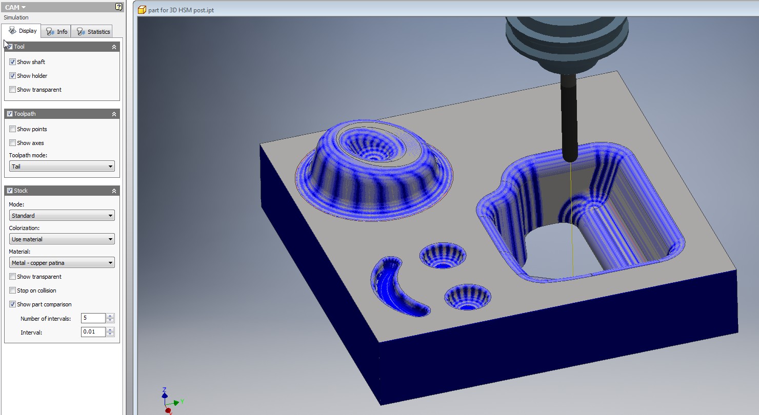
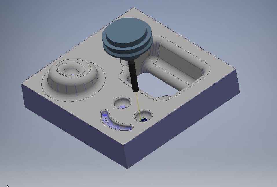
Notice the amount of material left in strange ways in the second screen capture. Regarding the first one by the way apparently the faceting you see primarily going down in Z is graphics card related and kind of self defeating. In an effort to reduce the GPU overhead by giving exact results it can fudge them a bit to reduce rendering times by reducing accuracy. Not a choice I would have made but there it is. I noticed the same thing with simulation in “metallic” mode with CW4SE and wonder if this is a common simulation program core both share or just the nature of graphics cards response to a situation.
Now look at simulation with settings changed and see a significant difference. First the relevant settings.
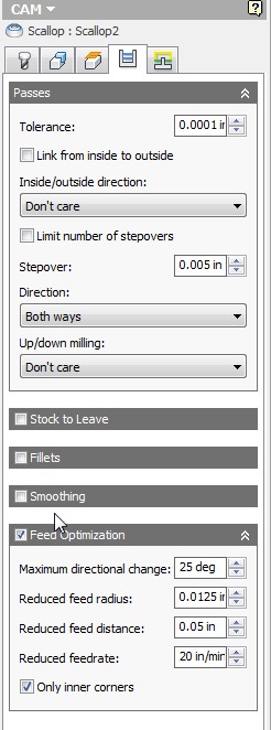
My problem was ticking the stock to leave box and picking .0001 and also selecting smoothing. Now smoothing sounds great depending upon which tool tip you see. Initially when I moused over “Smoothing” this is what I saw.

Sounds like no effect upon accuracy but this is not true. This is where I stopped looking and selected smoothing. However when you mouse over smoothing tolerance you get a different story.
Smoothing does effect accuracy and the tool tips depending on what you see first are misleading. I was told that smoothing was primarily a concession to older controllers that would have data starvation problems and that newer machines with better look ahead capabilities would not need this.
What I had unknowingly introduced was tolerance discrepancy stack-up and the difference was as large as adding each factor I had introduce in. .0001 + on material left and then whatever accumulated from the interpolation of the smoothing algorithym. Lets look at simulation results now with smoothing and material left not selected.
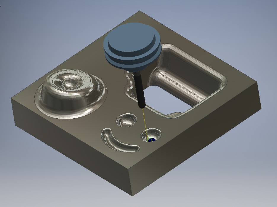
Pretty significant difference in my book and this was a self induced inaccuracy trap I had fallen into. Pay attention to these settings and you won’t have to scratch your head like I did wondering what is wrong.
